Cable tray type selection
What type of cable tray should be used for the main runs of a cable tray wiring system? The cable tray types to choose from are ladder, ventilated trough, or solid bottom. What are the reasons for selecting a specific type of cable tray?
The engineer or designer should select the type of cable tray that has the features which best serve the project's requirements.
For a few types of installations, the National Electrical Code (NEC) specifies the cable tray type to be used:
Single conductor cables and Type MV cables must be installed in ladder or ventilated trough cable trays. Single conductor cables and Type MV cables are not allowed to be installed in solid bottom cable trays.
In Class II, Division 2 Hazardous (Classified) Locations (Dust), the types of cables that are allowed to be installed in cable trays must be in ladder or ventilated trough cable trays. Solid bottom cable trays are not allowed to be installed in Class II, Division 2 locations.
Ladder Cable Tray
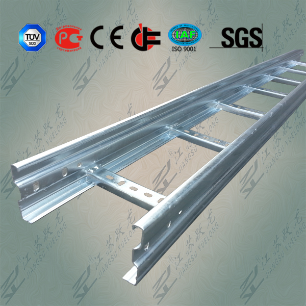
Ladder cable tray is used for about 75 percent of the cable tray wiring system installations. It is the predominate cable tray type due to its many desirable features:
A ladder cable tray without covers permits the maximum free flow of air across the cables. This allows the heat produced in the cable's conductors to effectively dissipate. Under such conditions, the conductor insulation in the cables of a properly designed cable tray wiring system will not exceed its maximum operating temperature. The cables will not prematurely age due to excessive operating temperatures.
The rungs of the ladder cable trays provide convenient anchors for tying down the cables in the non-horizontal cable tray runs or where the positions of the cables must be maintained in the horizontal cable tray runs. This capability is a must for single conductor cable installations. Under fault conditions (short circuit), the magnetic forces produced by the fault current will force the single conductor cables from the cable tray if they are not securely anchored to the cable tray.
Cables may exit or enter the ladder cable trays through the top or the bottom of the cable tray. Where the cables enter or exit conduit, the conduit to cable tray clamps may be installed upright or inverted to terminate conduits on the top or bottom of the cable tray side rail.
Moisture can't accumulate in ladder cable trays.
If cable trays are being installed where working space is a problem, hand access through the cable tray bottom may help to facilitate the installation of small diameter cables: control instrumentation, signal, etc.
The most common rung spacings for ladder cable tray is 9 inches. This spacing may be used to support all sizes of cables This spacing is desirable for the small diameter Type PLTC and TC cables as the support distance is such that there is no visible drooping of the small cables between rungs. 12 or 18 inch rung spacing provides adequate cable support but the slight amount of small diameter cable drooping between rungs may be aesthetically objectionable for some installations. The maximum allowable distance between supports for 1/0 through 4/0 AWG single conductor cables is 9 inches.
Ventilated Trough Cable Tray
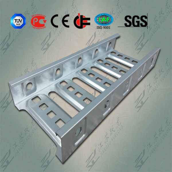
The only reason to select a ventilated trough cable tray over a ladder type cable tray is aesthetics. No drooping of small cables is visible. The ventilated trough cable tray does provide more support to the cables than does the ladder cable tray but this additional support is not significant. It doesn't have any impact on the cables service record or life.
Solid Bottom Cable Tray
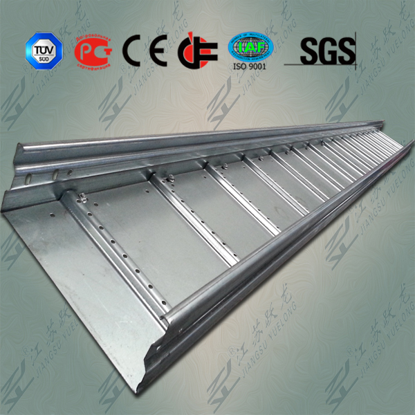
The main reason for selecting solid bottom cable tray (with covers) is the concern of EMI/ RFI shielding protection for very sensitive circuits. A solid bottom steel cable tray with steel covers provides a good degree of shielding if there are no breaks or holes in the completed installation.
The solid bottom cable tray system has a disadvantage in that moisture can build up in the cable trays. This can be controlled by drilling 1/4 inch drain holes in the bottom of the cable tray at three foot intervals (at the middle and very near the sides) if the cable tray is not being used for EMI/RFI shielding.
Some engineers and designers specify solid bottom cable trays (often with covers) in the belief that all electrical circuits have to be totally enclosed by metal. The cable trays are just supporting cables that are designed for such installations. Cable failures in cable tray runs rarely happen. Cable failures due to cable support problems in cable trays are nonexistent.
Information about
- Cable tray installment
- Cable tray selection
- How to see the cable tray layout whether qualified
- Non-metallic cable tray
- Cable tray market capacity is big
- Advantages of using cable trays instead of conduit
- Choosing right cable tray
- Cable trays adapt to changing needs
- How to choose cable tray
- What is the function of ladder cable tray?
Hot Sale
Top articles
- Cable tray installment
- Cable tray selection
- How to see the cable tray layout whether qualified
- Non-metallic cable tray
- Cable tray market capacity is big
- Advantages of using cable trays instead of conduit
- Choosing right cable tray
- Cable trays adapt to changing needs
- How to choose cable tray
- Cable tray type selection


